I've decided to try my hand at droplet and splash photography. Rather than using a manual method (setting up a constant drip method and trying to snap a picture the moment a droplet lands), I decided to go the engineered route (surprise!).
I did a lot of searching around on the interwebs, and found a lot of material on DIY setups, but none were really ideal for my particular use case, some were missing information, and a few were downright unsafe. So I decided to build my own system from scratch.
At first, I attempted to use the Raspberry Pi 2 as the controller platform, but I wasn't really happy with the results. It didn't have analog pins (useful for the photoresistor), and it wasn't really as fast as I wanted.
So instead of the Raspberry Pi 2, I decided to go with an Arduino Uno that I had lying around, which worked perfectly!
The hardware that I used for this project came from a few different sources:
Adafruit
Sparkfun
DigiKey
Amazon
Goal:
Automatically trigger a photograph of an object after it passes through a laser/photoresistor trap.
Solution:
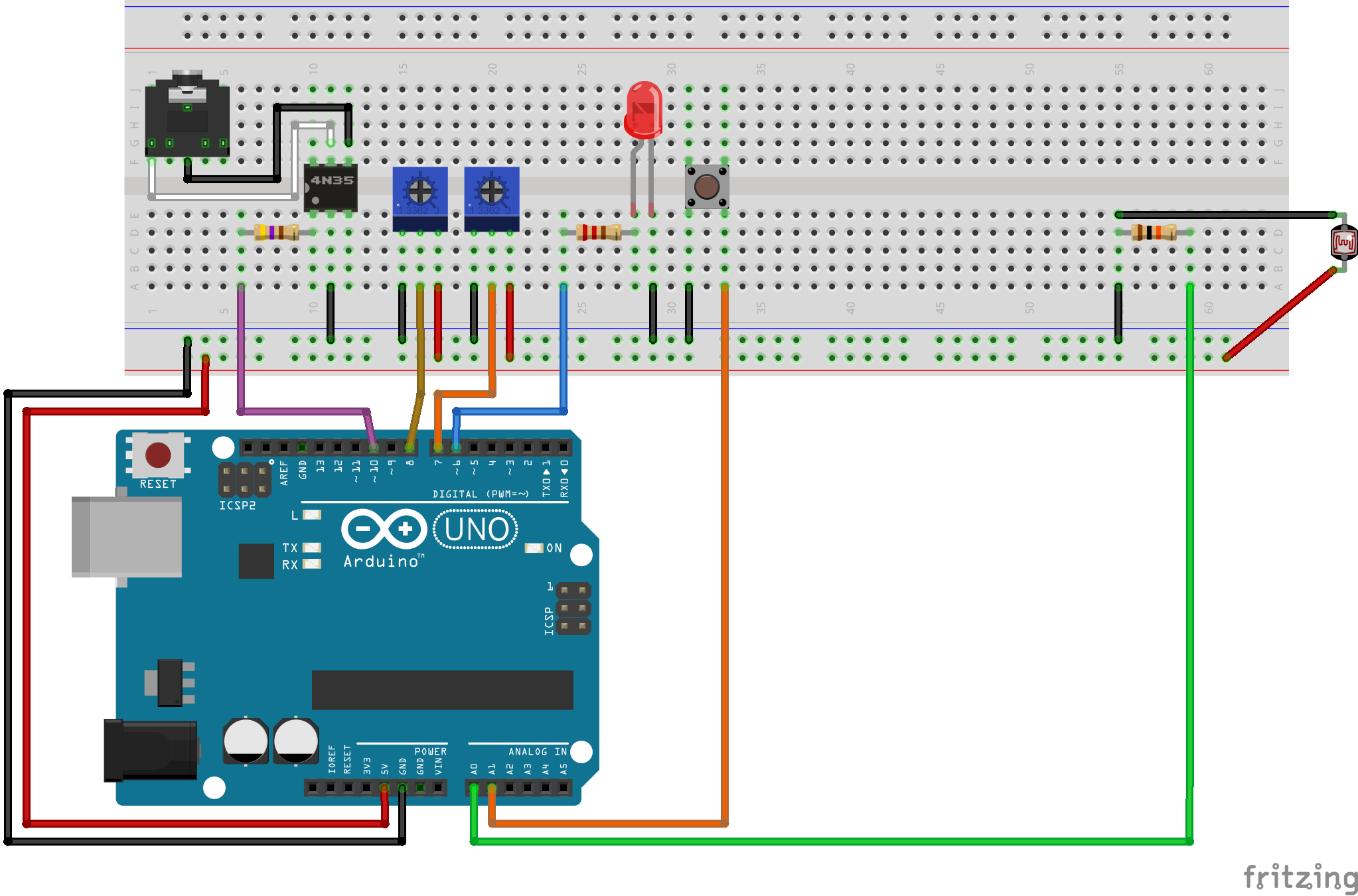
- Trimpot1 is used to dial in the 10s of milliseconds of latency between light interruption and camera firing.
- Trimpot2 is used to dial in the 1s of milliseconds of latency between light interruption and camera firing.
- A 5mW laser is aligned at a photoresistor. TacButton1 will enable and disable the laser (not shown on the diagram) using port 5 on the Arduino.
- When the laser is on target, causing the sensor to max out its reading at 1024, LED1 will turn on, providing a visible sign that the laser trap is ready.
- When an object passes between the laser emitter and the photoresistor, it will cause the resistance to drop slightly.
- The drop in resistance will trigger the loop which fires the camera through the 4N35 optocoupler after the number of milliseconds dialed in by the trimpots has expired. The optocoupler triggers the camera via a 3.5mm stereo jack, the other end of which is connected to the camera's N3 port via a stereo to N3 cable.
I'll post an Arduino sketch when I have everything prettified, as well as some actual photos!